The excavator controller is called the "brain" that controls the machine, and it plays a vital role in the normal operation of the excavator. It collects various information which will then be compared, calculated, and processed and output, and the engine speed is controlled to coordinate and match the action of the hydraulic system.
Each type of excavator has a controller, but the installation location is quite different. For example, for Komatsu, it is on the right rear side of the cabin, for Hyundai 220-5, under the left hand joystick, and for Caterpillar 320, generally outside the cabin, beside the battery.

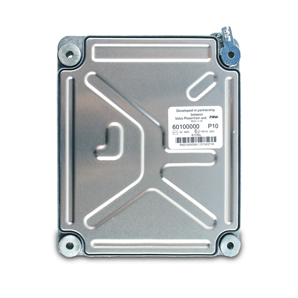
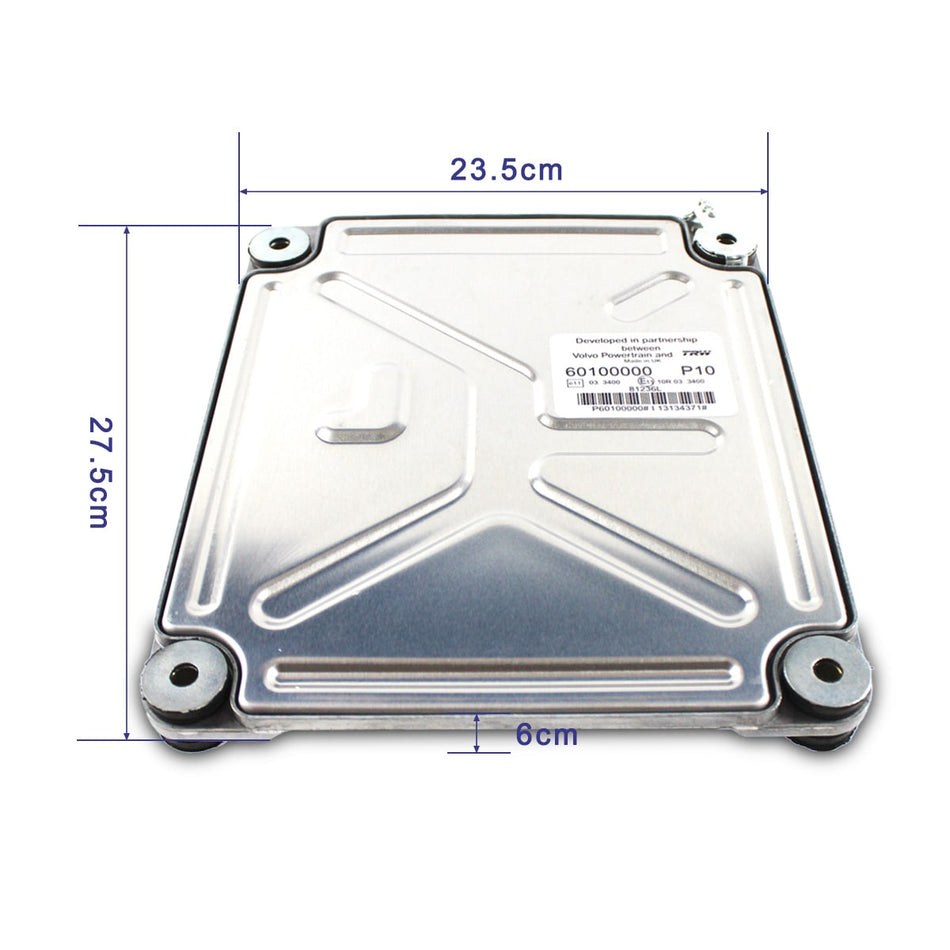
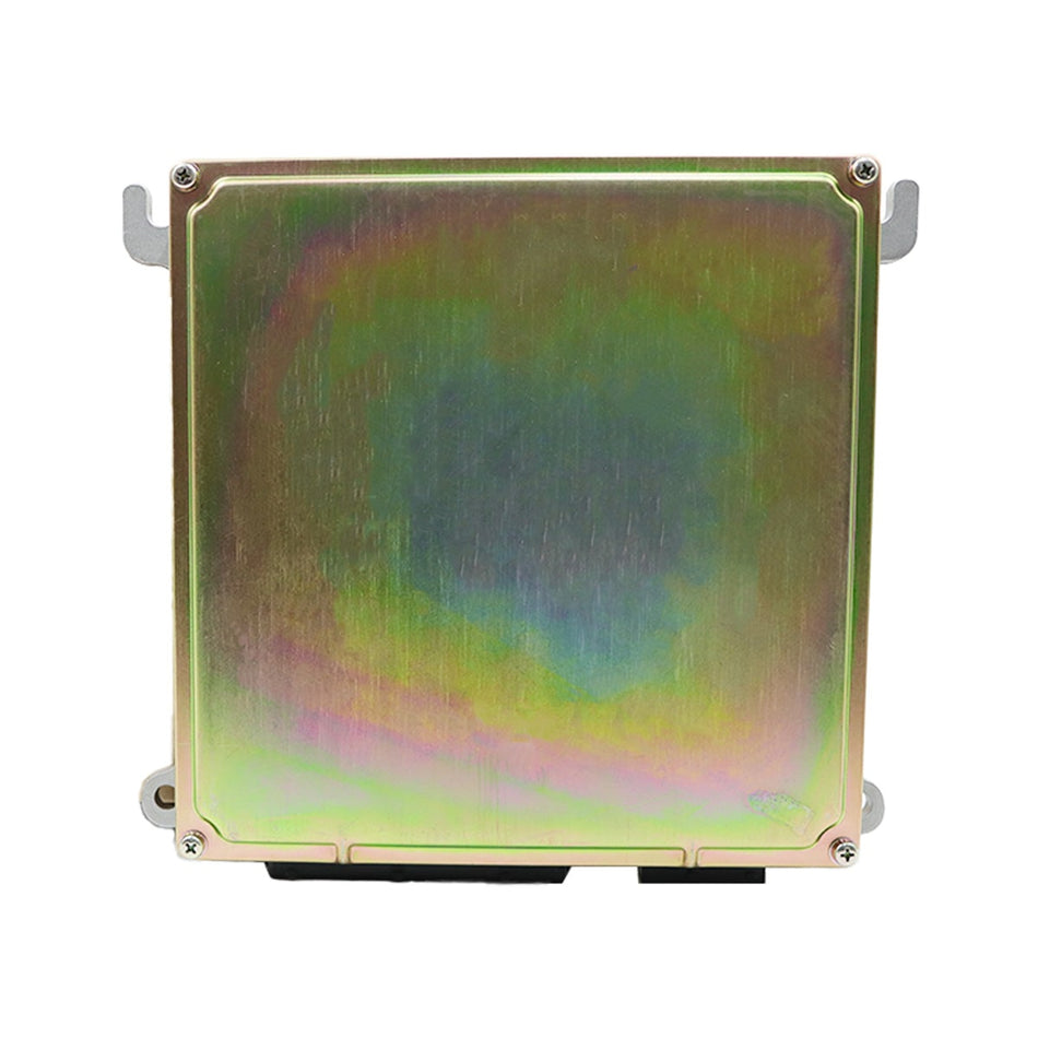
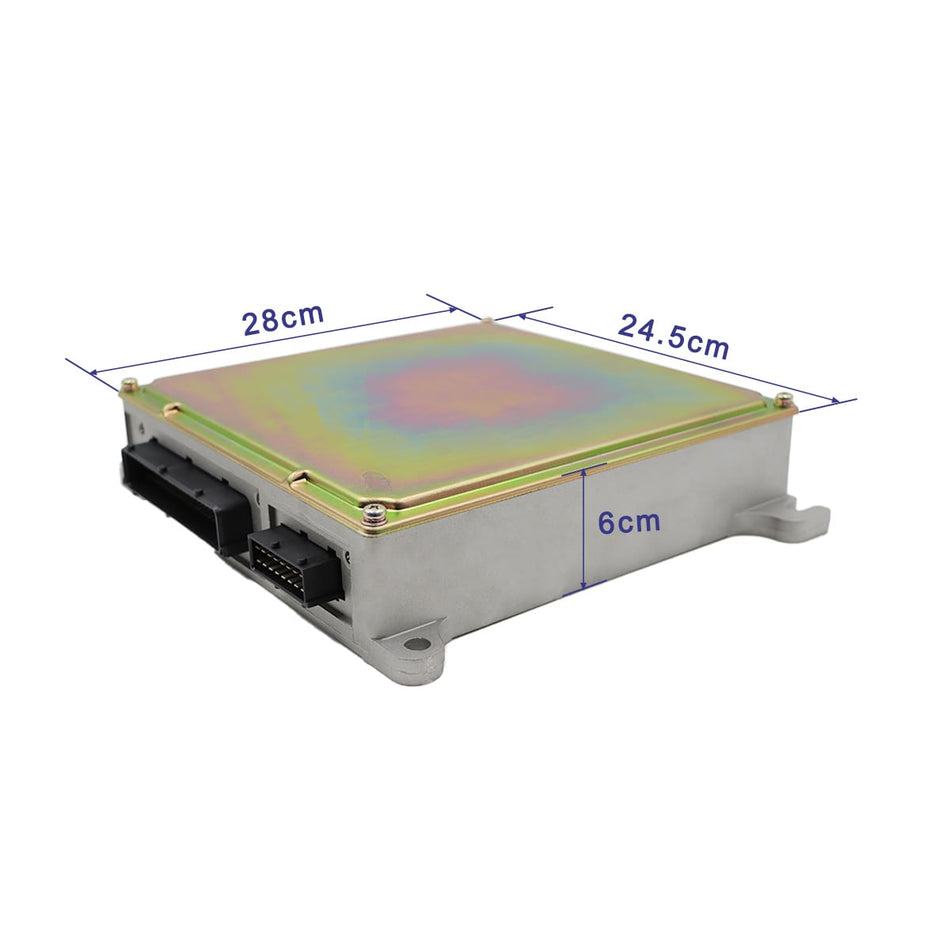
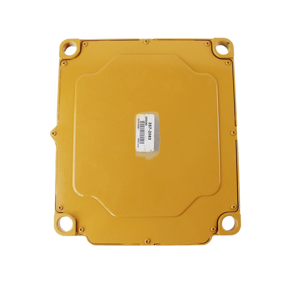
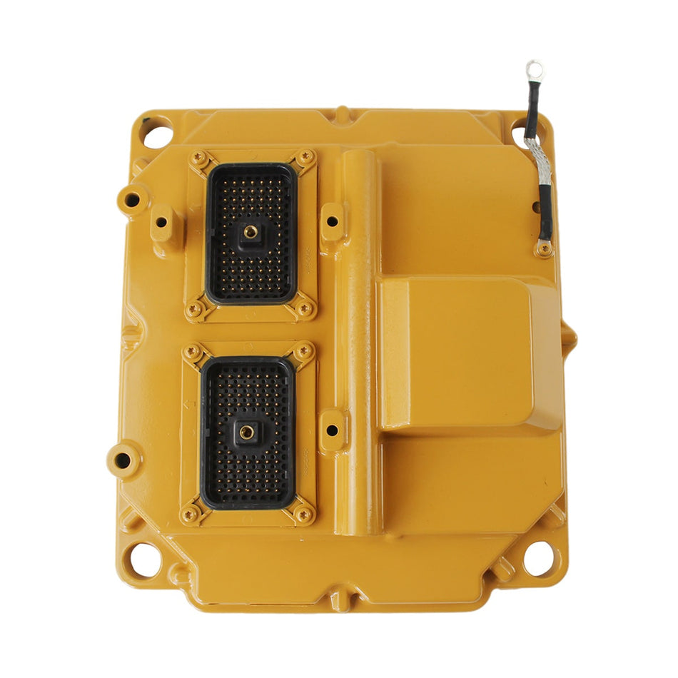
SINOCMP Controller for Cat 320
1. Function description
1). It is possible to replace the throttle controller of excavator brands that use DC motors (such as Daewoo, Hyundai, Xugong, Liugong, Lonking, Sunward Intelligent, Xiagong, Foton Lovol, Sany, etc.). The electronic throttle function and the hydraulic board are on the same controller. If the throttle part is damaged, you can also put in a universal throttle board to replace the electronic throttle function).
2). Peripheral wiring as shown in the figure above, requires an external power supply, 2 pressure switches, throttle knob potentiometer, throttle motor, and steering sensor. You can have electronic throttle function by wiring as shown above.
3). The throttle can be added or subtracted by the throttle knob. After turning on the automatic idle switch, if the steering is above about 1200 rpm, the automatic idle speed adjustment will be performed after 5 seconds. When one of the conditions of the pressure switch, automatic idle switch, and throttle knob changes, it will exit automatic Idle speed to the position set by the throttle knob.
4). Different engines have different flywheel teeth, so the reverse signal detection will be different.
5). The pressure switch is a normally open type. That is, when the pressure switch is pointing, it is a necessary condition for automatic idle speed. When the pressure switch is turned on, it will exit the automatic idle speed when it is grounded.
6). The calibration sensor connection only needs to be parallel, that is, there is no need to overlap the original car line, only need to peel off the original car calibration sensor harness and parallel the two wires.
2. Factors that cause damage to the controller
The most common reasons for controller damage are water and mechanical impact. In addition, lightning strikes, welding surges, pin corrosion, internal components ablation, etc. can also cause controller damage. The usual way to prevent welding surge is to disconnect the power supply of the whole machine, that is, cut off the battery switch. Some manufacturers even require users to disconnect the controller and the wiring harness of the whole machine before using electric welding. The most common cause of pin corrosion is poor sealing performance of the large plug of the controller, which causes moisture to penetrate, and the accumulation of time eventually causes pin breaks or poor contact.
Controller damage generally has the following situations:
1). The generator malfunctions, causing high voltage in the circuit.
2). The battery is connected in series when the user starts the engine.
3). Unauthorized connection of electrical appliances will increase the electrical load and burn out due to excessive current.
4). The generator regulator fails, causing the generator to generate too much power.
5). The battery positive and negative poles are connected wrongly, the wiring harness is aging, and the short ground is poor.
6). Do not repair according to operating specifications, plug and unplug the ECM with power on.
7). The excavator cuts the cable and suffers an external high voltage electric shock.
8). Misuse of fuses with large capacity.
9). Water enters the controller, causing a short circuit.
10). Incorrect wiring or improper plugging of the controller.
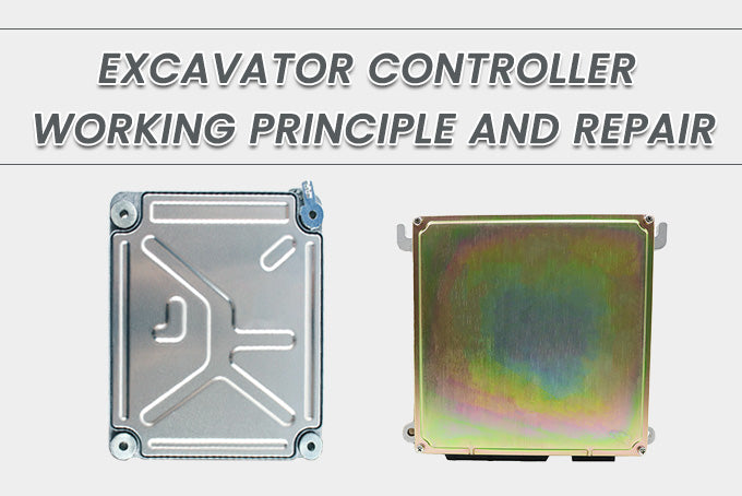
 controller repair
3. Basic steps of controller repair
To repair a relatively unfamiliar circuit board without any schematic diagrams, the so-called "experience" in the past is very useful. Although the use of online circuit maintenance testers has greatly increased the probability of repairing the circuit board, if the method is improper, Work with half the effort. So, what can be done to improve maintenance efficiency? Summarize the following principles:
Principle 1: Look first and then measure
Use tools: digital (or analog) multimeter, magnifying glass
When holding a circuit board to be repaired, a good habit is to first visually inspect it, and use a magnifying glass when necessary. What should you look at? Mainly look
1). Is there any disconnection? Are there any signs of burning?
2). Are discrete components such as resistors, capacitors, inductors, diodes, transistors, etc. disconnected?
3). Is there any breakage or adhesion on the printed circuit board connection line on the circuit board?
4). Has anyone repaired it? What components have been moved? Are there any operational errors such as false soldering, missing soldering, and reverse insertion?
After confirming that the repaired board does not have the above conditions, first use a multimeter to measure the resistance between the power supply and the ground of the circuit board. Usually the resistance of the circuit board is above 70-80Ω. If the resistance is too small, only a few or a dozen One ohm means that there are components on the circuit board that are broken down or partly broken down, and measures must be taken to find out the broken down components. The specific method is to supply power to the repaired board and touch the temperature of the components on the circuit board with your hands. The hot ones will be the key suspects.
If the resistance is normal, you can use a multimeter for fault detection. Because there are many factors that cause the circuit board to fail, measure the resistance, capacitance, diode, triode, field effect tube, dial switch and other discrete components on the board. The purpose is to first ensure that the measured components are normal and repair The principle is that if you can use a multimeter to solve the problem, don't complicate it.
Principle 2: First outside, then inside, enumeration test
Tools used: HY circuit online maintenance tester series, marker pen
Because each model of the HY circuit online maintenance tester series integrates two fault diagnosis technologies, one is the standard comparison test method based on the device test library (ie ICFT); the other is the real-time comparison scan test based on the VI curve Method (ie ASA-VI).
When using ICFT for chip test, the following two test blind areas may appear:
1). The test program library has not yet established a test program for a certain chip, that is, there is no such chip in the library.
2). Even though the test program library has established the test program of the chip, the "online test" fails.
The controller of the excavator is rarely damaged during normal use. It is not a vulnerable part, and is generally caused by man-made or force majeure. The general causes of force majeure damage are lightning strikes and ultrasonic interference. The working environment of excavators is complex, harsh and varied, and there are many reasons for the damage to the controller. Taking preventive measures in advance is the first thing.